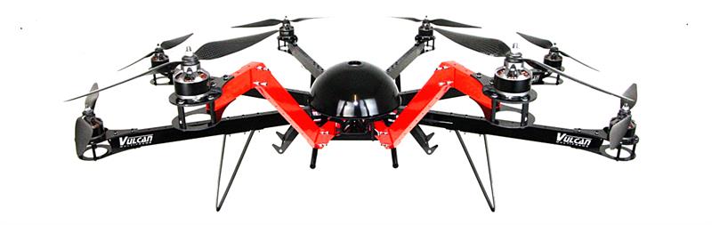
The Vulcan concept is one of strength, simplicity and flexibility of design. To achieve this we have focussed on the primary functions of any multirotor airframe – to hold the motors in the desired confirguration, to be lightweight yet stiff and avoid the transmission of vibration, to provide a solid base on which to install your electronics and payload, good space for your power systems to be fitted and remain cool, to be simple to assemble and maintain, to be strong enough to offer considerable resistance to damage in the event of an accident, and should damage be sustained, to be simple to repair at a very reasonable cost. To achieve this we have used a combination of sound design and quality materials aimed at avoiding the common problems experienced by many other frame designs, as well as offering simple assembly, durability and a flexibility of configuration not seen in other aiframes.
Our first range of airframes was the MultiFrame series. Whilst our products have come a long way since the MultiFrame was released, much of the thinking behind the design still holds true with our current systems
To understand some of the thinking behind what we make, here is what we said back in the day when the MultiFrame series was first released…
Flexibility:
One of the first things considered during the design of the MultiFrame, was that there was no good reason for the user to be stuck with one particular frame layout, chosen at the point of purchase and before they have had a chance to try that configuration and decide if it is suitable for their needs. So for ultimate flexibility, the MultiFrame uses the same few parts in all frame configurations, allowing the user to change their frame at any time, simply by moving, adding or removing arms as they wish – and without losing the orientation of the frame centre section, battery tray and standoff plates, thus avoiding a lengthy complete reinstall of all onboard systems.
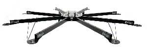
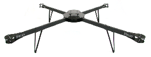
Configurations of the MultiFrame include Y6, + Quad, X Quad, X8, I Hexa, V Hexa, I Octo and V Octo.
Landing legs can be easily fitted to any arm, and moved anywhere on that arm, not only to accomodate the different frame layouts, but also to provide the best balance between stability on landing, balance in the air and a clear camera view.
Battery tray and standoff plates are interchangeable, and you can stack as many standoff plates as you like to hold all flight electronics, sensors, cameras, receivers, transmitters, datalinks, GPS, OSDs and other onboard equipment, providing some distance and shielding between them, so helping to minimise RF and magnetic interference.
Motor mounts can be fitted to the top or bottom of the arm, or fitted in pairs to allow two motors per arm to be used.
The arms are drilled at 30mm intervals to allow flexible mounting of the landing legs, and a variety of other equipment such as video transmitters, mini cameras, LED strips and camera mounts. With the motor and frame centre mount holes also at 30mm spacing, the arms can also be easily cut in 30mm sections to allow the user to change the rotor diameter of the frame to their own preference.
Power System Installation:
One of the biggest issues with most frames is that not enough consideration has been given to the installation of the main power systems. The space is too small, or badly laid out leaving you with a rats nest of wires and ESCs crammed together in a very small space. There will always be limited space in these machines, so installation will always be tight, but having all your main power systems forced into a small space can lead to very high temperatures during operation – and high temperatures and sensitive electronics are never a good combination, and can lead to premature failure! The MultiFrame allows for a simple installation, excellent cooling for your ESCs and access to them and their connections without taking the frame apart. The plate spacing is such that most ESCs will fit between the frame plates on their sides, so can be attached to the side of each arm with foam tape. This allows very good airflow around the ESCs, and the ability to simply pull them out and get access to their connections should you need to. Very useful when setting motor rotation direction!
There is room for most common power distribtuion boards to be mounted at the centre fo the frame, although mounting holes for these are not pre drilled as the exact mounting hole spacing varies from board to board.
Construction:
As with most high end muticopter frames, the MultiFrame uses highest quality Carbon Fibre as the main construction material for it’s well known strength and light weight, and we have carefully chosen our material weave and thickness to provide the stiffness, rigidity and durability needed for a heavy lift machine.
Unusually we decided to use aluminium alloy for the construction of the arms. Carbon Fibre is very strong in certain directions, and when it comes to any kind of hollow tube, it has great longitudinal strength, but is very easy to crush. To mount a Carbon Fibre arm, an internal brace, sleeve or spacer must be used, or a friction mount that presses evenly around the entire outside of the tube. Although it is possible to crush the aluminium alloy arm section, it has much greater strength in this direction making straight through bolt mounting possible. The MultiFrame arm section is custom moulded from quality aluminium alloy with a wall thickness not normally available in this type and size of moulding, allowing it to provide the required strength with light weight, as well as minimise vibration transmission.
The square section not only allows easy mounting of arms, plates, motor mounts etc, but avoids problems common to arms that do not have a good flat surface, such a rotational vibration, the twisting of arms in their mountings, or twisting of motor mounts on the arm. Even a small loss of orientation in the arm can cause all sorts of problems during flight!
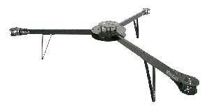
The standard V landing legs are made from light weight aluminium strip, very strong in a downward and outward direction. They are however designed to give in a heavy sideways landing situation, reducing the possibility of damage to the arm. With a double bolt at the rear and a single bolt at the front of the leg, in the event of heavy sideways stress, they are able to twist at the front and bend round on themselves. This means that should you have a bad landing resulting in leg damage, the arms should remain straight, and the leg can be simply bent back to it’s original position. Whilst your landing leg may not be perfect after this, you should still be able to continue to fly, not ending your day due to one small error!
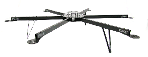
But how strong are they ?
We knew they were strong, but when the question was asked we had to find out! Here is an unedited photgraph taken at the end of a product shoot – the brick test!
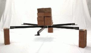
In this picture the Hexa is supported on three arms only, at full 1200mm span… and sitting on top of the centre plates are 28kg of house bricks. It could have taken more had there been more bricks available.
There was absolutely no damage sustained during this test, this exact frame is now flying regularly.