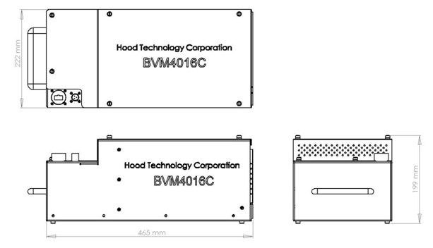
The data acquisition console takes the analog signals from the preamplifiers and turns them into timing data which can be interpreted into useful information. There are two families of Hood Technology Corporation’s BVM data acquisition consoles. The first is the model 8030, mounted in a self-contained 19” instrumentation rack. The newly developed model 4016C has integrated preamplifiers, a much smaller form factor and all solid state components. Versions of this system have been used in flight testing. Table 1 highlights the major differences between the two models.
Table 1: Comparison of data console models 8030 and 4016C.
| Model 8030 | Model 4016C1 | |
| Timing Resolution | 80MHz, 12.5ns ~ 4um at 340m/s rim speed | 40MHz, 25ns ~8um at 340m/s rim speed |
| Data Streaming | ~1.5Mblades/sec | ~0.25Mblades/sec |
| Maximum Channel Count | 30 | 16 |
| Outer Dimensions | 650mmX900mmX1100mm | 222mmX465mmX199mm |
| Weight | ~130kg | ~10kg |
| Virtual Oscilloscope | Yes, up to 1.2Msamp/sec Fast refresh rate | Yes, up to 0.5Msamp/sec ~ 1 second refresh rate |
| Preamplifiers | Separate | Integrated |
| Power Consumption | 185 to 550W | 60 to 120W |
| Power Requirement | 110-240VAC | 24-35VDC |
| Thermoelectric cooling of laser diodes | No | Yes |
1. BVM Model 8030
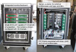
A photograph of a 30-channel version of BVM model 8030 is shown in Figure 1. This system hosts 1 to 10 BVSI modules, each supporting a Hood Tech preamp and 3 channels of sensor data.
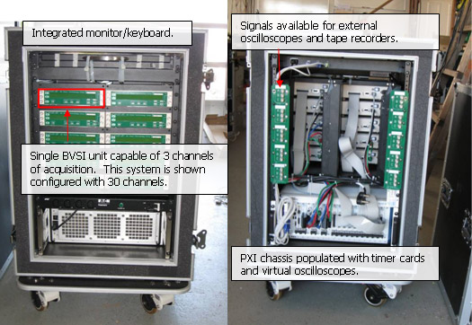
Figure 1: Model 8030 data acquisition console. Standard 19 inch rack is soft-mounted. Console is on casters and has removable front and back lids for shipping and safe storage.
The Blade Vibration Sensor Interface (BVSI) unit, developed by Hood Technology Corporation ( Figure 2 ), conditions analog blade passage signals and converts them to a digital signal, which is precisely timed. The BVSI performs the following functions:
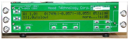
Figure 2: Blade Vibration Sensor Interface (BVSI) conditions the analog blade passage signals and converts them into precisely timed digital signals.
Table 2: BVSI Parameters and their associated ranges or possible values.
| Parameter | Min Value | Max Value |
| Gain | -25 | 25 |
| High Pass Filter Cutoff | 0 Hz | 3397 Hz |
| Low Pass Filter Cutoff | 23 kHz | 1496 kHz |
| Offset | -7 V | +7 V |
| Arm level | 0.055 V | 4.995 V |
| Trigger Edge | Rising/Falling | N/A |
| Trigger Level | 0 % | 90 % of max value attained |
| Hold Off | 0.2 µs | 4984 µs |
| Decay Rate | Slow/fast | N/A |
2. BVM Model 4016C
Blade vibration monitor model 4016C was developed in 2008/2009. The cabling diagram, shown in Figure 3, is somewhat different than model 8030. The 4016C has all the features of the BVSI, BV-IND, and BV-OP integrated in a single box. In use, it would be located near the sensors. Rather than run cables with power and signal to the acquisition console, only an Ethernet cable is required to transmit data to a ‘ground station’, which could simply be a laptop computer running Acquire Blade Data. The figure also shows a flight-test implementation with a telemetry link. The first use of this system was in flight test of a military aircraft.

Figure 3: The cabling diagram of the BVM model 4016C is somewhat different than Model 8030, because the BVSI and preamplifier are integrated into one box that is located near the sensors. Data are streamed to disk, via UDP or TCP/IP. The “ground station” can be simply a laptop connected with an Ethernet cable.
 粤公网安备 44010602004357号